Quick Navigation
Warning:
Activate features only if wiring exactly follows these instructions. Incorrect wiring can damage the ECU and/or engine.
Additional Cooling — Wiring / Installation / Operation
SWAPParts
- Additional cooling pump: ONLY original Pierburg CWA200 (N54/N55) is supported.
- Additional coolant fans: Any fans with PWM input or relayed activation are supported.
Wiring
T_TEV is used as the PWM input for the AUX water pump.
Disconnect the tank vent valve and run the cable to the CWA200 according to the diagram.
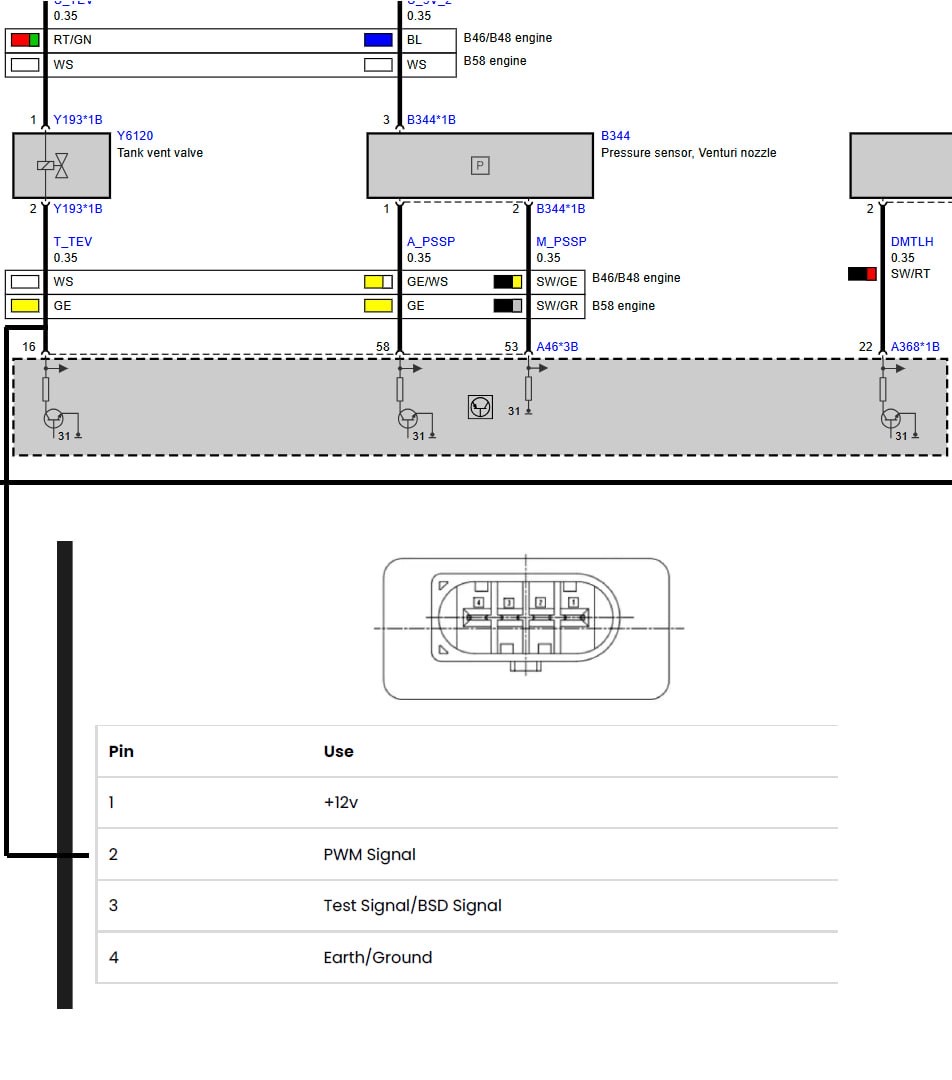
Figure: Additional Cooling wiring diagram
Operation
According to mapping.
Switched Antilag — Wiring / Installation / Operation
SWAPWiring
Route the antilag switch between M_DOPF and A_DOPF.
- OPF-enabled car: Cut the wires at the X13*13B plug and run them to the desired switch location.
- Non-OPF car: Use OEM pins (BMW P/N 61139230107) to add them directly to the A368*1B ECU main connector.
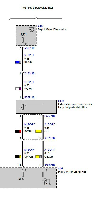
Figure: Switched Antilag wiring diagram
A detailed video instruction will be posted and linked here later.
Operation
A_DOPFpulled high = function disabled.A_DOPFpulled low = function activated.- When the clutch pedal is pressed, RPM will rise to the setpoint per mapping and the engine will build boost.
Automatic gearbox support is coming later. Currently designed for MT race cars with clutch input.
Adjustable by mapping.
Torque Knob — Wiring / Installation / Operation
SWAPWiring / Installation
Use any potentiometer from 10 kΩ to 100 kΩ as the torque control knob.
M_PSSP→ one side contact of potentiometerU_5V_2→ the other side contact of potentiometerA_PSSP→ middle (wiper) contact
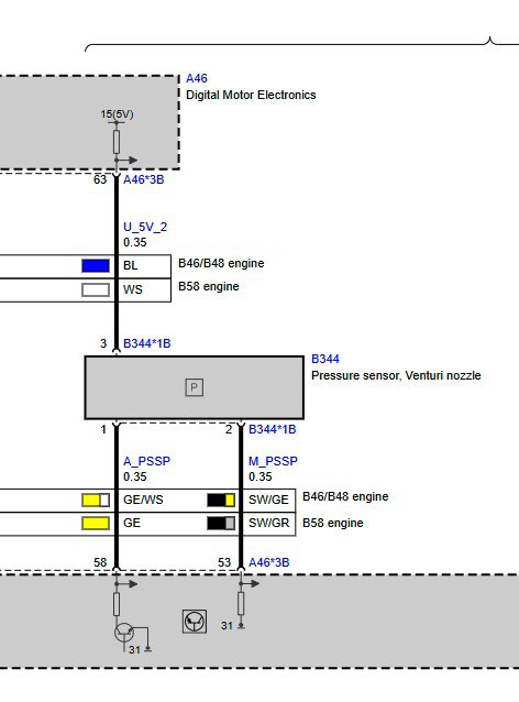
Figure: Torque Knob wiring diagram
Operation
According to mapping.
Last updated: 14.08.2025 • For support: contact@1769.fi